
The current study focuses on the critical contribution that working circumstances make to the performance and lifespan of reformer tubes used in the Direct Reduced Iron (DRI) process. We look in depth at tube failures brought on by hot patches, localized overheating, and uneven thermal gradients throughout the tube. Eddy Current Testing, Diametric Tube Growth/OD Profilometry, and Tube Wall Temperature (TWT)/Tube Metal Temperature measurement are just a few of the inspection and monitoring approaches being investigated to meet these difficulties. Notably, it is advised to sometimes use IR Pyrometric temperature Imagers to make sure that the temperature gradient profile along the tube’s length is good. Life Cycle of reformer tubes.
To further avoid catalyst breakage and guarantee optimal plant performance, emphasis is placed on constant monitoring of input gas temperature and steam-to-carbon ratio. The pressure decrease across the tube must be measured and monitored often to ensure safe functioning. During plant operation, it is crucial to visually examine all tubes and note any anomalies, such as hot spots, bending, or changes in tube color. In-depth logs of visual inspections should be kept, coupled with IR Thermal Images for TWT measurement, and frequently reviewed. To deal with any discovered anomalies, the knowledgeable Technical Team must conduct an immediate investigation. By putting these complete safeguards into place, reformer tube operation will become safer and more effective, improving plant performance and tube life. Life Cycle of Reformer Tubes
Introduction
The Steam Methane Reformer, also known as the Reformer, is a crucial component found in various industrial plants such as Ammonia, Refineries, Methanol, and DRI steel plants. It is an expensive and energy-intensive equipment within the plant. Essentially, the Reformer is a furnace with NiCr tubes filled with Nickel Oxide catalyst, where the steam reforming reaction occurs at high temperatures. This reaction involves the conversion of methane in natural gas into hydrogen and carbon monoxide with the aid of catalysts and superheated steam [1]. Life Cycle of Reformer Tubes
The Reformer tubes, made of Nickel and Chromium alloy modified with Niobium/Titanium metals, are highly resistant to high temperatures, creep, and oxidation. However, prolonged operation and abnormal conditions like plant shutdowns can lead to various defects, deformations, and degradation in the tube material, ultimately resulting in tube rupture and plant shutdown. To ensure economic viability, safety, reliability, and structural integrity, it is crucial to periodically identify and quantify these issues to prevent catastrophic tube failures that cause production loss and refurbishment expenses [1]. Life Cycle of Reformer Tubes
The MIDREX reformer, used in this specific paper, differs from the steam reformer used in Ammonia plants and petrochemicals in several aspects. It reforms both carbon dioxide and water vapor, operates at a specific oxidant/carbon ratio, operates at low pressure, and requires a unique catalyst design. The paper discusses the advantages and limitations of state-of-the-art non-destructive testing (NDT) inspection techniques. It also emphasizes the importance of closely monitoring certain operational parameters to prevent tube failures, considering the significant role of skilled plant operation. Real-world tube failure examples are included to support the content of the paper [1-2] Life Cycle of reformer tubes
Tube metallurgy and design
The Reformer tube is a crucial and costly component of the Reformer. Due to its operation in high-temperature environments, the tubes are manufactured using temperature and corrosion-resistant alloys such as Cr, Ni, and Fe. They are centrifugally cast to achieve the desired metallurgical structure and meet stringent material requirements. The addition of Niobium (Nb) as a micro-alloy provides increased resistance to high creep. Incorporating Titanium (Ti) as a micro-alloy allows for the use of thinner tubes while maintaining a tube life of 100,000 operating hours. By using micro alloyed tubes with minimum wall thickness, the catalyst volume can be increased, thereby enhancing plant capacity.
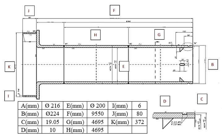
The typical dimensions of the tubes used in DRI steel plants are illustrated in figure 1. The metallurgical composition of the top and bottom tubes is selected to suit bottom firing requirements. Life Cycle of Reformer Tubes
Bottom Section: Centralloy G 4852 (HP+Nb) Cr 25 Ni 35 Nb 1.5 + balance others
Top Section: Centrally G 4879 (HP+Ti) Cr 28 Ni 48 Ti 5 + balance others (Higher Cr content improves oxidation resistance, while higher Ni reinforces the effect of chromium on oxidation-reduction and provides greater mechanical and structural stability).
In oxidizing environments with high oxygen content, the aforementioned alloys rely on the formation of an oxide film to resist corrosion. However, as temperature increases, the rate of oxidation also increases, which can be detrimental. To achieve improved oxidation resistance, it is common practice to increase the chromium content. Life Cycle of Reformer Tubes
The radiant tube, extending between the furnace ceiling and the floor, is composed of top and bottom sections that consist of butt-welded segments measuring approximately 4-5 meters in length [3]. Life Cycle of Reformer Tubes
Tube Failure Mechanism
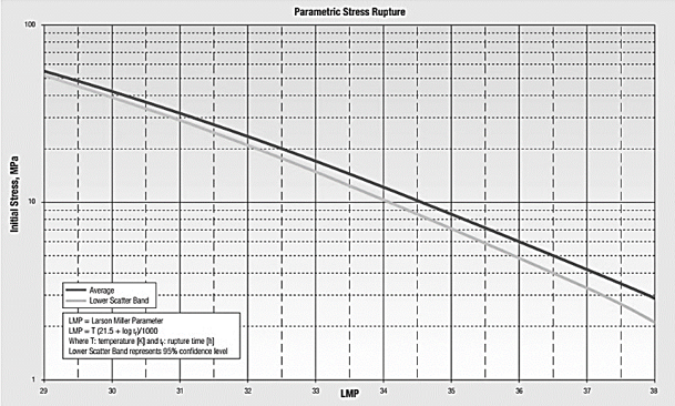
The catalyst tubes in a Reformer are typically designed to have a lifespan of 100,000 operating hours. However, with conservative operating conditions, it is possible to achieve service lives as high as 180,000 operating hours or even longer. Nevertheless, even under safe and conservative operating conditions, the tube material undergoes degradation due to prolonged exposure to high temperatures, leading to the formation of creep cracks. Creep refers to the time-dependent and continuous plastic deformation of the tube material over extended periods when subjected to constant thermal and pressure stresses. Creep cracks usually occur at temperatures higher than 0.4 times the melting temperature (Tm) of the material. Apart from steady-state thermal stresses (temperature difference between the inner diameter and outer diameter surfaces), the tubes experience pressure stresses caused by the weight of the catalyst and the pressure of the feed gas inside the tube. This results in longitudinal elongation and circumferential growth of the tube. These thermal and pressure stresses are known as primary stresses. In other words, the pressure and thermal stresses experienced under normal plant operating conditions are referred to as primary stresses. Tube manufacturers define and predict a design tube life of 100,000 operating hours by considering all steady-state primary stresses. shocks occurring during unscheduled plant tripping and unsafe plant start-ups in quick succession. Also, since tubes operated very close to the design maximum temperature hence at times tube temperature may exceed the maximum design temperature due to plant mis-operation. The stresses developed due to exposure to a temperature greater than the design temperature and also due to abrupt thermal shocks (shutdowns and start-ups) are referred to as Secondary Stresses. Catalyst degradation also contributes to secondary stresses. The rate of creep damage increases drastically when subject to secondary stresses and may cause premature rupture of the tube much before the guaranteed life span. Tube manufacturers during the design stage conduct several rupture tests at different temperatures and represent the data in the form of a Larsen-Miller Curve (Figure2) [4]. Larsen Miller Parameter is [5]: Life Cycle of reformer tubes
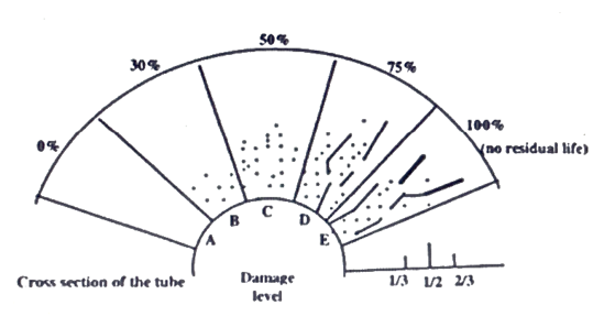
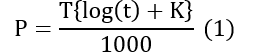
Where T= Temperature t= Time K= Constant. Larsen Miller curves are generally used for calculating remaining life assessment. Creep damage occurs typically at inner diameter/mid-wall thickness and propagates further towards the OD surface. Creep damage occurs over a major portion of the tube circumference over a longer (axial) portion of the tube resulting in budging and cavitation. Final rupture occurs in the longitudinal direction (Figure 3).
This figure exhibits how creep voids are developed which over a period of time get aligned and form creep cracks. Creep at weld joint develops at center line of weld deposit (heat affected zone of butt weld) starting from inner surface approximately at 1/3rd of tube wall thickness. The manufacturers do the inspection of a few samples only from each lot of casting and not every tube they manufacture. Therefore, there is every possibility of the presence of metallurgical defects viz. voids, fissures which over a period of time get aligned and form cracks even under normal plant operation. Therefore, the customer should always insist on 100 percent inspection of each and every tube and should ask for inspection reports for every tube. Life Cycle of reformer tubes
Creep defects are manifested in many ways :
*Creep Elongation and Rupture
*Brittle Failure due to thermal shocks (thermal fatigue) due to repeated shutdowns and start-ups in quicker succession.
*Bowing (Buckling) and bulging of tubes
*Metal dusting and Carburization on ID surface.
*Defects during the manufacturing stage of tubes
And the root cause of most of creep damages is unsafe operation at very high temperatures and abrupt thermal shocks. Thus, we conclude that tube metal temperature (TMT) plays a crucial influence on tube life span. Therefore, it is very important to measure TMT accurately as far as possible and closely monitor it. We shall discuss this further under “ Inspection and Monitoring Techniques” [6].
Inspection and Monitoring Techniques
The inspections are crucial because tubes can fail even within their designated lifespan. By monitoring the health condition of the tubes during major plant shutdowns, the operations staff gains confidence in the remaining useful life of the tubes. This allows them to make informed decisions about refurbishing tubes based on their actual health condition rather than relying solely on time-based criteria. Refurbishment based on actual health conditions is more cost-effective, as there have been instances where tubes have served well beyond 180,000 operating hours. Two types of inspection techniques are mentioned: Destructive Testing (DT) and Non-Destructive Testing (NDT). Destructive testing involves damaging the tube material, making it unserviceable for future use. These tests are typically conducted during manufacturing or post-failure analysis in laboratories. In contrast, several NDT tests have been developed for in situ inspection of tubes. Table 1 shows some NDT techniques widely used around the world.
There are several inspection methods used for in-situ evaluation of creep strains among them Ultrasonic, Eddy Current, and Laser profilometry three most widely recognized approaches accepted the world over [7]. Life Cycle of Reformer Tubes
Eddy Current Testing technique
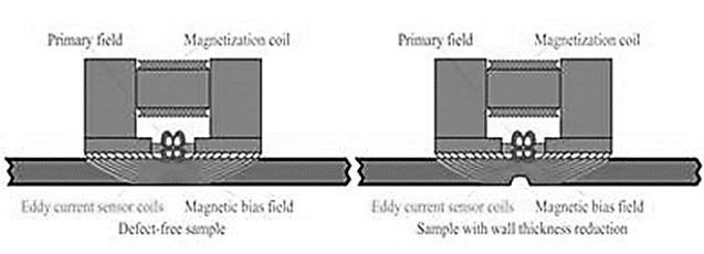
Eddy’s current testing uses the principle of electromagnetic induction to identify flaws and discontinuities in ferrous and nonferrous materials. The impedance of the coil changes when an eddy current flows through the material, indicating the presence of flaws or discontinuities.
There are several inspection methods used for in-situ evaluation of creep strains among them Ultrasonic, Eddy Current, and Laser profilometry three most widely recognized approaches accepted the world over [7]. Life Cycle of Reformer Tubes
The ECT probe has a limitation in that it can encompass a limited area of tube circumference. The Eddy Current Array probe can partially saturate the inspected area and can be excited at different times and at different frequencies.
ECA can detect creep defects through the entire tube thickness and can encompass larger tube circumferences.
ECA is the most preferred technique for tube remaining life assessment. It is used to measure tube exterior dimensions (Figure 4) [8]. Life Cycle of reformer tubes
Diametric Tube Growth / OD Profilometry
Recently the use of laser profilometry has gained wider acceptance because this also provides early detection of early-stage creep development. During the initial stage of creep damage, the inner surface of the tube OD begins to expand or swell. The use of laser profilometry provides accurate mapping and quantification of a tube OD as several hundred thousand diameter readings are acquired along the entire length of the tube (figure 5). Life Cycle of Reformer Tubes
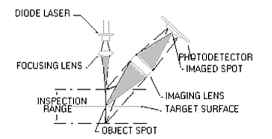
The above figure shows the fundamental theory of laser profilometry for diametric growth evaluation. Using a Focusing Lens the beam from the Laser Diode is projected onto the internal surface of the tube. The photodetector then sees the laser reflection through the Imaging Lens, generating a signal proportional to the spot’s position on the detector. The image on the photodetector shifts as the distance between the target surface and the light source changes. Generally, dual axis (four lasers) are used and for more accuracy, three axes (six lasers) are used Simultaneous with the diametric measurement, the tube thickness can also be determined. A separate graphical representation can be made of the tube thickness by changing the resolution scale. Failure due to diametric growth Since reformer tubes are long and closely spaced vertically anchored within the reformer furnace it poses problems to performing various NDT inspections as described above. Therefore it is very difficult and time-consuming to perform above mentioned NDT inspections [9]. Life Cycle of reformer tubes
Tube Wall Temperature (TWT) / Tube Metal Temperature
Accurate Tube wall temperature measurement and monitoring continuously is an important parameter in the design and operation of steam reformers because it is very crucial for prolonging the lifetime of tubes, for process optimization, and more importantly for reforming process efficiency. There is a paradox: the plant operators try to maintain a temperature high enough close to the design temperature to ensure greater plant efficiency while on the other hand, the designed lifetime of tubes gets rapidly deteriorated even at a slight increase from the maximum design temperature of the tube. The industry rule of thumb is that a 20°C increase in tube wall temperature above its maximum design temperature will halve the tube life. So, plant operators maximize production by operating as close as possible to the temperature limits without exceeding the design temperature. However, it is very tricky to measure and monitor accurate tube wall temperature because tubes receive radiant heat energy from refractory surfaces inside the furnace and also because of endothermic reforming reaction taking place inside the reformer tubes.The most common and widely used temperature-measuring device is a thermocouple. Life Cycle of reformer tubes
Thermocouples are usually welded onto the tube surface or embedded in the tube wall and connected to a recorder or DCS panel. They are simple and inexpensive for temperature measurement and provide temperature measurement at a point (or spot temperature). Also due to weld mass (if welded) and due to embedment within the tube they do not detect actual tube temperature. Not only that they tend to drift and are difficult to recalibrate. Another major limitation is that they were difficult to shield against furnace radiations and therefore give erroneous temperature readings. In case thermocouples fail while in service can not be replaced unless the furnace shut down.Due to the above-described limitations, it is strongly suggested to cross-check temperature readings with Non- contact “Infra-Red pyrometers and thermal imagers once or twice in a shift. Single-point pyrometers and Thermal Imagers both are non-contact types and work on the same Infrared principle. They measure infrared energy both emitted by the tube surface and reflected from the refractory. Then the amount of infrared energy received is converted into a temperature reading. Single-point pyrometer gives spot reading whereas Thermal Imagers or Cameras gives the thermal image of an entire field of view and provide a complete thermographic image of the entire field of view of the camera instead of one spot. Thus, both these pyrometers measure the sum of two: reflected radiation superimposed on thermal energy emitted by the tube surface. Hence, temperature compensation against radiated IR energy has to be compensated to obtain the actual tube wall temperature. This is referred to as emissivity correction and is generally programmed into the software of the instrument itself [10]. Life Cycle of reformer tubes
The sole purpose of above described NDT inspection methodologies and techniques is to determine the present condition of tubes and to determine the extent of creep damage developed within tube material and then thereby determine the remaining useful in the service lifetime of tubes in order to avoid unexpected catastrophic failures of tubes while in service The designed tube life as specified by the tube manufacturers is in fact creep rupture strength (i.e. the stress that causes rupture of the tube); generally of 100000 in-operation hours. During the manufacturing stage, the manufacturers conduct numerous tube rupture tests under varied stress and temperature conditions for long hours of time in their laboratories. Such rupture tests are very time-consuming and use expensive test instruments. These numerous laboratory test data are graphically represented and known as Larsen Miller curves as shown below. The NDT inspection service provider uses the Finite Element Analysis software model program which is specifically developed for each and every different tube metallurgy to determine thermal and pressure stresses based on UT, ECT tube inspection data. FEA software model also uses Larsen Miller Curves and Larsen Miller Constant supplied by tube manufacturer for the tubes under study. This FEA is a very complicated software model which considers numerous other parameters and also NDT inspection data did earlier on similar metallurgy tubes. The study and development of such a highly specialized software model are beyond the scope of this paper. Here it is sufficient to mention that using this FEA model the service provider determines/predicts the remaining healthy life of the tubes.
Needless to say, the RLA study is of immense importance to plant operators and plant management to avoid any in-service catastrophic failures of tubes resulting in huge financial losses because of loss of production and expensive refurbishing of tubes. It also helps to extend the useful service life of tubes beyond the design life of 100000 operating hours.
Briefly following steps are involved while determining the useful remaining life :
1. Tube Data: Tube material, Operating Temperature, and other relevant plant operating parameters.
2. Tubes in-service time
3. Refer to the Larson Miller curve provided by the manufacturer
5. From the curve find out thermal stresses at the tube operating temperature and also at elevated temperature say about 20o Celsius higher than the operating temperature.
6. Determine Larson Miller Parameter (LMP) for the material and predict time to failure using LMP
7. Predict the time for failure based on LMP [11].
Suggestions for safe & efficient plant operation
The temperature of the tube wall is a critical factor that can cause tubes to fail prematurely. Such failures can occur due to localized overheating, also known as hot spots, or uneven thermal gradients along the length of the tube. Misalignment of burners, flame impingement, and other factors can cause localized overheating while measuring temperature using thermocouples alone may not be sufficient to detect uneven thermal gradients along the tube’s length. To ensure a good thermal gradient profile across the entire length of the tube, it is strongly recommended to periodically use IR Pyrometric Thermal Imagers. Uneven thermal gradients may also cause the tube to bow or bulge .*Additionally feed gas temperature is to be continuously monitored. Steam to Carbo Ration to be continuously monitored to avoid catalyst breakage within the tube. Catalyst dust will lead to high resistance to feed gas flow ( low flow of feed gas) resulting in hot spots. Pressure drop across the tube is to be regularly measured and monitored.To ensure the safe operation of the plant, it is important to avoid frequent abrupt tripping and only allow senior experienced plant operators to perform plant start-ups. During the operation of the reformer, it is necessary to conduct visual inspections of all tubes at least twice per shift through the peephole windows. These inspections should note any abnormalities, such as hot spots, bowing, or changes in tube color. A separate record should be maintained for each tube’s visual inspection .*Audit of Visual inspection records and TWT as measured by IR Thermal Images to be done periodically and any abnormality in records immediately to be investigated by the expert Technical Team of the plant [12].
Conclusion
In conclusion, Non-Destructive Testing (NDT) provides accurate data on the performance and quality of plant components, including reformer tubes in DRI plants. NDT methods are simple, inexpensive, and non-invasive, making them an attractive option for plant life assessment. The benefits of NDT include improved safety, reduced downtime, improved productivity, cost savings, and consistent product reliability. Automated NDT systems can provide greater flexibility and speed, but require a large initial investment. Overall, the use of NDT for remaining of reformer tubes in DRI plants can provide numerous benefits, including improved safety, reduced downtime, and cost savings.
References
[1] Ravindranath, K., Akbar, A., Al-Wakaa, B., & Abdallah, Z. (2022). Creep Failure of 25Cr-35Ni Centrifugally Cast Reformer Tube. In IntechOpen eBooks.
[2] Holland, M. L., & De Bruyn, H. (1996). Metal dusting failures in methane reforming plant. International Journal of Pressure Vessels and Piping, 66(1–3), 125–133.
[3] Tu, S., Segle, P., & Gong, J. P. (2004). Creep damage and fracture of weldments at high temperature. International Journal of Pressure Vessels and Piping, 81(2), 199–209.
[4] Tawancy, H. M., Ul-Hamid, A., Mohammed, A., & Abbas, N. M. (2005). Failure analysis of catalytic steam reformer tubes. Anti-corrosion Methods and Materials.
[5] Chang, M., & Lin, Y. (2012). Creep Life Prediction of 9Cr-1Mo Ferritic Steel with Larson-Miller and Manson-Haferd Parameter. Advanced Science Letters, 15(1), 53–57.
[6] Zhao, J., Peng, Z., Cui, D., Li, Q., Jieguang, H., & Qiu, J. (2019). A Method for Measuring Tube Metal Temperature of Ethylene Cracking Furnace Tubes Based on Machine Learning and Neural Network. IEEE Access, 7, 158643–158654.
[7] Zečević, N., & Bolf, N. (2020). Integrated Method of Monitoring and Optimization of Steam Methane Reformer Process. Processes, 8(4), 408.
[8] Yang, Q., Xie, S., Kun, H., Yue’e, C., Chen, Z., Uchimoto, T., & Takagi, T. (2021). A novel circumferential eccentric eddy current probe and its application for defect detection of small-diameter tubes. Sensors and Actuators A-physical, 331, 113023.
[9] Feng, S., Zuo, C., Zhang, L., Tao, T., Hu, Y., Yin, W. H., Qian, J., & Chen, Q. (2021). Calibration of fringe projection profilometry: A comparative review. Optics and Lasers in Engineering, 143, 106622.
[10] Pasha, A. A., Al-Harbi, M. a. O., Halkarni, S. S., Islam, N., Reddy, D. S. K., Pillai, S. N., & Qadiri, U. (2021). CFD study of Convective Heat Transfer of Water Flow Through Micro-Pipe with Mixed Constant Wall Temperature and Heat Flux Wall Boundary Conditions. CFD Letters, 13(7), 13–26.
[11] Guguloth, K., Swaminathan, J., Bagui, S., & Ray, A. K. (2012). Remnant Life Assessment and Microstructural Studies on Service Exposed Primary Reformer Tubes of a Catalytic Converter of anAmmonia Plant. High Temperature Materials and Processes, 31(6), 759–767.
[12] Duarte, C. A., Espejo, E., & Martinez, J. A. (2017). Failure analysis of the wall tubes of a water-tube boiler. Engineering Failure Analysis, 79, 704–713.
Authors : Matin Pashakhanloo1 , Abbas Parsa1 , AmirHossein Yousef Beigi1 Ashwani B Motwani 2
Affiliations 1- Vista Aseman Company , Iran